Low Voltage DC grids
Operational and Protection Aspects of Local Direct Current Networks
Electricity grids around the world are changing. Distributed generation from renewables, charging infrastructure, and battery energy storage systems are added to existing networks. Power electronic converters play a major role in these technologies - And they all work internally with Direct Current (DC).
As the existing power grids are based on Alternating Current (AC), additional conversion steps are necessary for connection. Local DC grids are an approach to improving overall system efficiency and reducing material usage. There are, however, substantial differences between AC and DC power grids to be considered. The following elaborates on some operational and design aspects of low voltage DC grids.

History
Power grids are changing: Low Voltage DC Grids

While the fundamental principle of power transformers remains the same today as in the early days of electrical power networks, the technology has evolved: Transformers became ever more efficient and with on-load tap changers, the transformer ratio can be controlled.
In the 20th century, power grids based on AC were built around the world. However, DC grids never ceased to exist: DC kept being used in special applications such as electric railways or - with the availability of efficient power electronic components - high-voltage direct current (HVDC) transmission systems.
Impulse article: Direct current at all grid levels
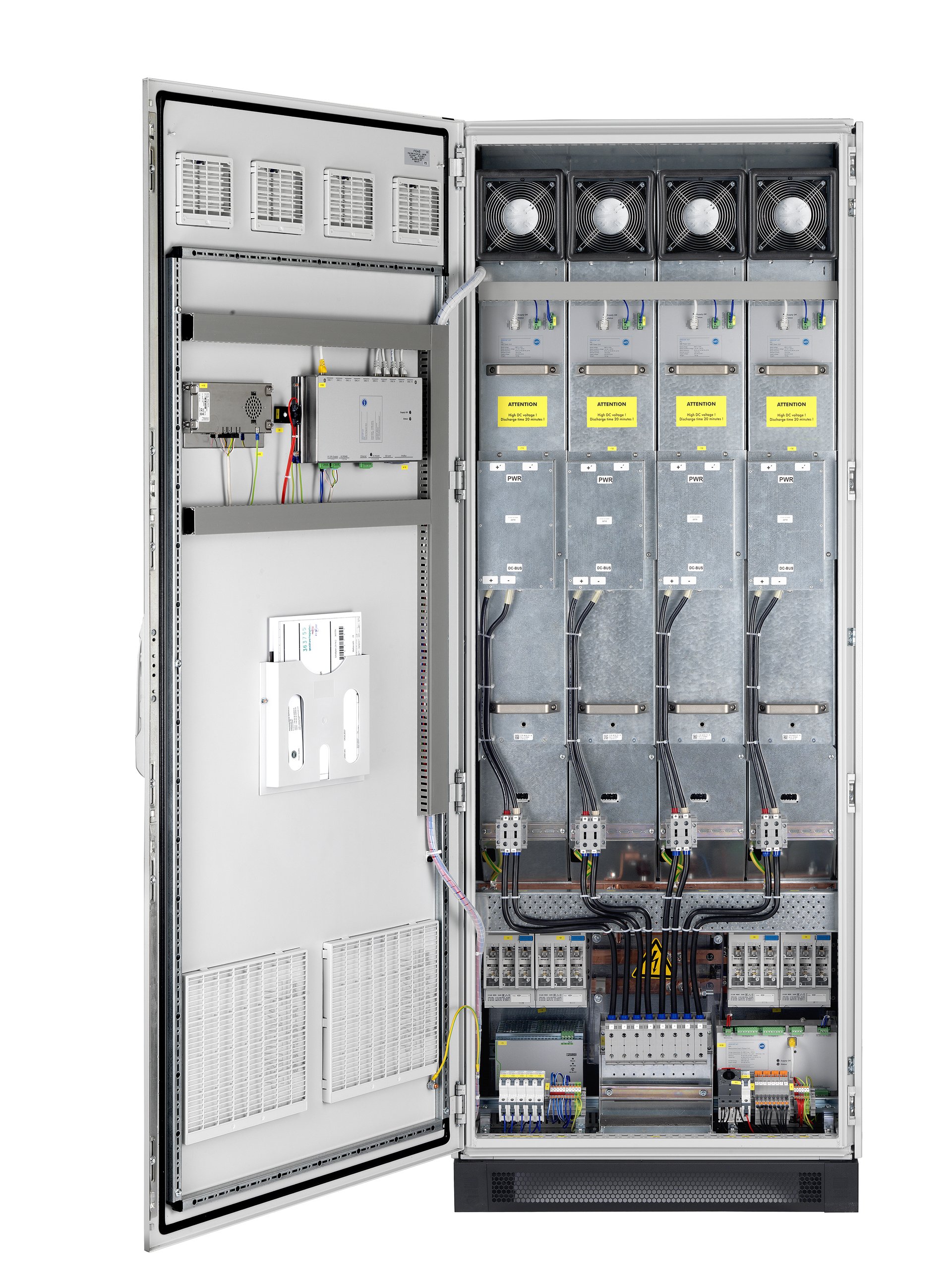
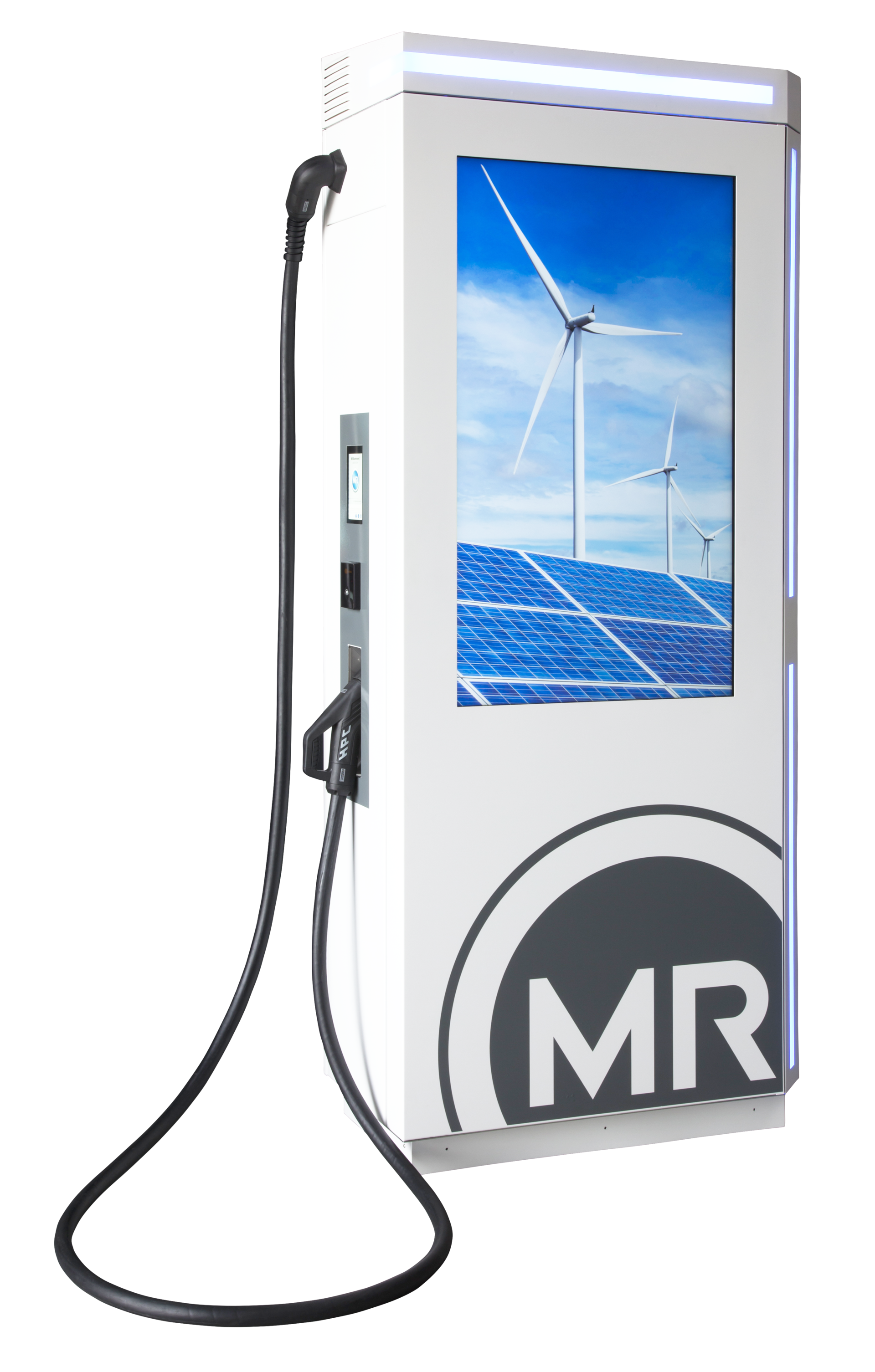
In recent years, low voltage DC grids have sparked the interest of the academic and industrial community. A key driver are high-power charging systems for electric vehicles. Such systems charge car batteries with relatively high DC currents – In many places, the power demand during a charging process exceeds the capacity of the existing power grid. It needs to be expanded with new cables and transformers. Stationary battery storage systems are an alternative to grid expansion. They are charged and discharged with DC. The efficiency of a system comprised of batteries and DC charging stations can thus be increased by connecting them directly via DC – avoiding conversion to AC and back.
Other systems that function internally with DC include:
-
Variable-frequency drives
-
Heat pumps
-
Uninterrupted Power Supply systems
-
Electrolyzers for e.g. green hydrogen
-
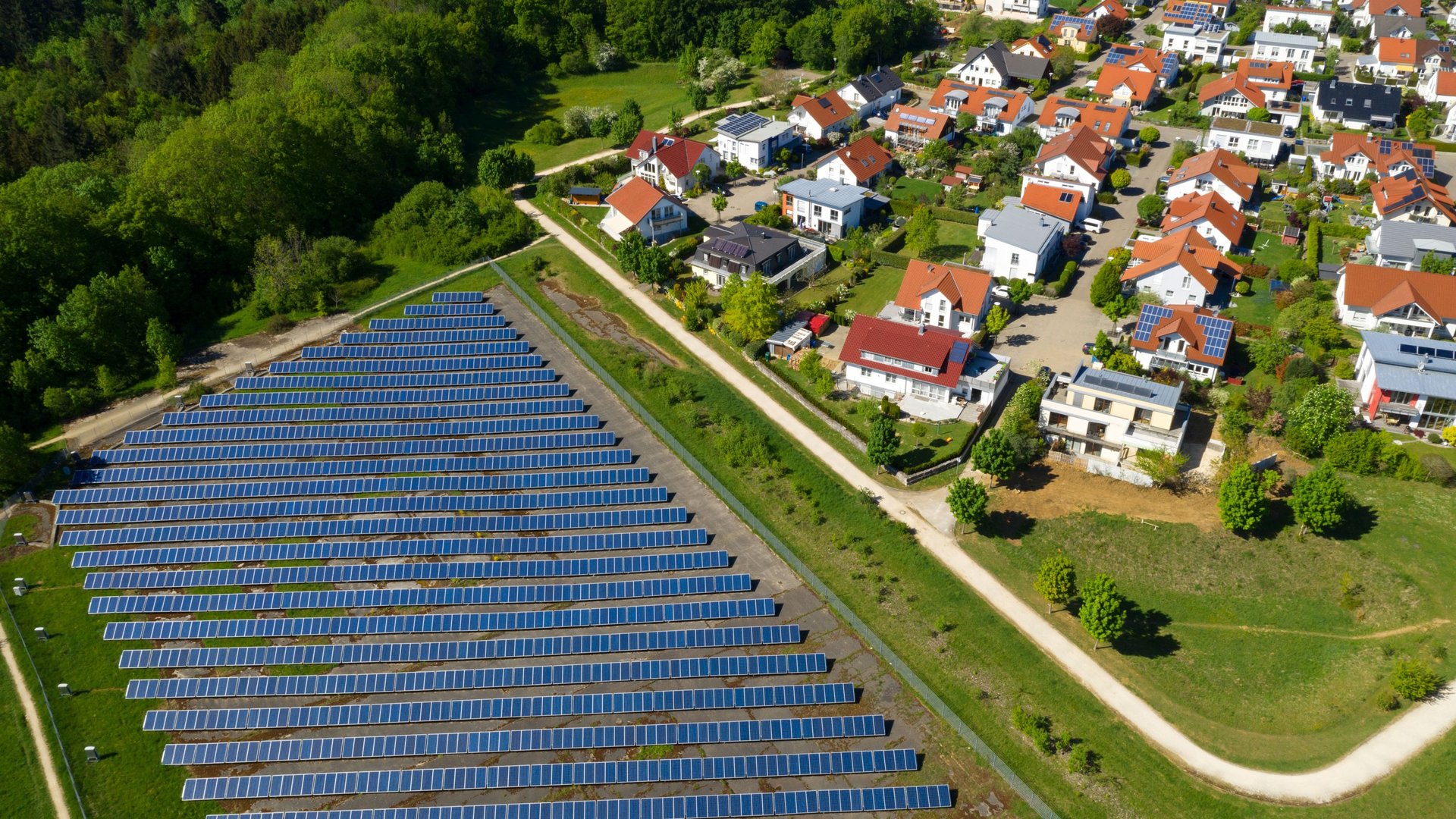
Photovoltaic systems
-
Wind turbines
| AC | DC | ||
| Power Quality | Harmonics propagate through the AC grid and lead to additional losses due to eddy currents, skin effect | No harmonics | |
| Synchronization | When AC networks are interconnected, they must be synchronized in amplitude, frequency and phase angle Synchronization is mandatory for the operation of power electronic converters on the grid |
Only the voltage amplitudes need to match for interconnection of DC grids | |
| Controllability | Voltage control via On-Load Tap Changers Special Phase-shifting transformers are required for power control |
Modern DC-DC Converters offer voltage, current and power control | |
| Efficiency | Reactive power flows increase losses in the power grid Conversion losses when integrating power electronic equipment into the grid (e.g. renewable energies) |
Less conversion stages in case of mainly electronic loads No reactive power No skin effect |
|
| Short-circuit protection | Wide range of proven products are available Inductors limit the current rise in event of short circuit |
The short-circuit current rises more quickly as only a purely ohmic line impedance is effective Due to this high current steepness and the lack of a zero crossing, new types of protection concepts are needed |
|
| Material usage | Dedicated systems for reactive power compensation are needed Power electronic equipment requires harmonic filters to maintain power quality |
Less conversion stages, hence less material required for filters and power converters Cables can be dimensioned with lower diameter, less conductive material (copper, aluminium) is required |
Transformers and the easy conversion between voltage levels played a key role in the victory of AC over DC. Modern technology however enables conversion between DC voltage levels – making use of power electronics. Similar technology is used in modern chargers for laptops and cell phones, both of which function internally with DC, too.
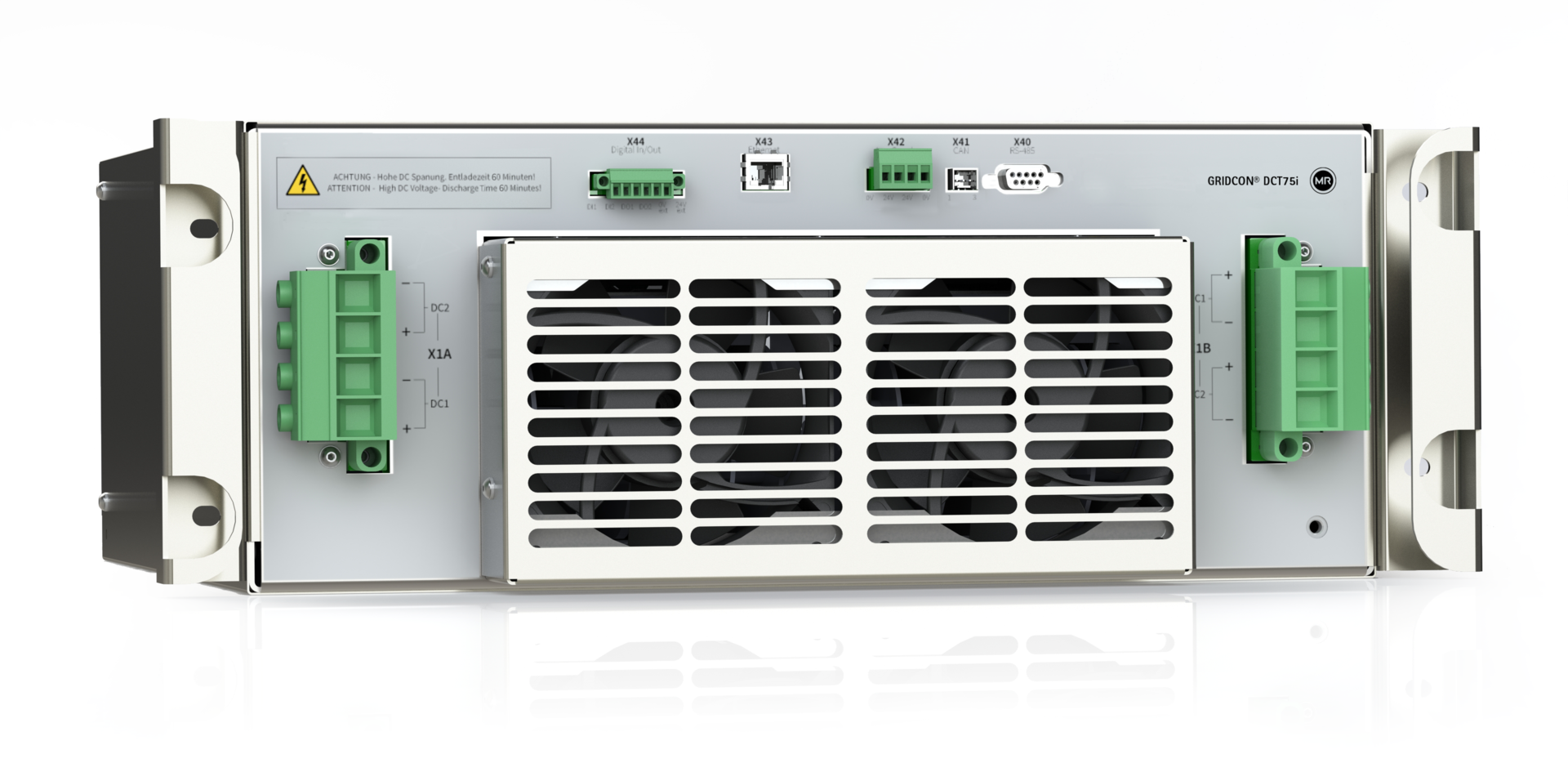
Stage 1: Controlled conversion from DC to medium frequency alternating rectangular voltage by power electronic switching elements S1-S4 (in this example: MOSFETs)
Stage 2: Transformer provides galvanic insulation. Compact design and low losses are achieved through medium frequencies (typically between 10 kHz and 100 kHz)
Stage 3: Controlled conversion to direct current by switches S’1-S’4
As the conversions in stage 1 and stage 3 are done by active elements, the power flow and DC voltages can be controlled.

Topologies: What is the difference between a unipolar and bipolar DC system?
In a unipolar DC system, two electrical potentials exist. Therefore, only two conductors are needed to connect a DC power source with a load. Bipolar systems comprise of three electrical potentials: DC+, 0, und DC-. Bipolar networks therefore require more conductors, but offer higher power with the same absolute voltage. Besides, a bipolar grid offers two voltage levels: VDC and 2*VDC for the connection of converters, battery cells, etc.

Unipolar system

Bipolar system
As with AC networks, grounding also plays an important role in ensuring electrical safety in DC systems. However, there are principle-related differences between the network types that affect the selection and operation of the grounding system. Leakage currents for instance play a larger role in DC networks. These are undesirable currents that flow into the ground - with the possible consequence that metallic parts are damaged by corrosion.
Grounding concepts for DC networks are listed below, along with their advantages and disadvantages.
Direct grounding
A simple and cost-effective method for grounding in DC systems is directly and constantly connecting one pole to earth potential.
In a unipolar system, it is common practice to ground the negative pole. Some considerations to do this are better protection in case of faults and less corrosion than if the positive pole was grounded. In directly grounded DC networks with bipolar configuration, the mid-point is generally connected to earth potential.

Bipolar system with mid-point grounding
Resistance Grounding
A resistor can be introduced to the grounding connection. This reduces stray currents and corrosion effects. However, additional components are needed and extra losses occur. Furthermore, grounding via a resistor must be taken into account when designing the protection concept.

Bipolar system with mid-point resistor grounding
Diode or Thyristor Grounding
This grounding scheme aims to combine the benefits of isolated networks with directly grounded systems. Connection to earth is established by a diode or thyristor switch in the event of a fault. In normal operation, the system is isolated. Thus, stray currents and corrosion are prevented. In the event of a critical fault, a connection to earth is established, improving personal safety. If a thyristor switch is used, a monitoring relay detects faults and activates the thyristor in the event of failure.

Bipolar system with mid-point thyristor grounding
Isolated System
In an isolated system there is no connection to ground potential. For this reason, the term floating grounding is also used. Insulation monitors must be used to detect errors. AC networks are often designed as an isolated system if continued operation is desired in the event of a fault. This doesn't apply to DC networks. Isolated systems are used here to simplify the parallel operation of different feeders.

Isolated system
Low voltage DC grids provide compelling advantages such as improved electrical efficiency and reduced material usage. However, there are less standards and best practices than for AC systems. The requirements for protection and grounding differ between AC and DC systems. In practice, isolated systems and mid-point grounding are used for newly designed DC networks, depending on the specific application.