On-load tap-changers for power transformers
On-load tap-changers (OLTCs) are indispensable in regulating power transformers used in electrical energy networks and industrial applications.
This content explains the technological developments of resistor-type OLTCs and reactor-type OLTCs. The general switching principles for OLTCs are discussed and OLTC applications are presented.
Today’s OLTC design concepts, including vacuum type OLTCs, are described. The vacuum switching technology used in OLTCs is the “state of the art” design now and in the foreseeable future. Examples of OLTC designs and the respective switching principles show the range of the usage of vacuum interrupters.

History
Power transformers equipped with on-load tap-changers (OLTCs) have been the main components of electrical networks and industrial applications for nearly 100 years. OLTCs enable voltage regulation and/or phase shifting by varying the transformer ratio under load without interruption.
Since the Scheubeck brothers produced the first prototype on-load tap-changer for Dr. Jansen in 1929, the company MR has been a driving force in the field of transformer developments.
From the start of tap-changer development, two switching principles have been used for load transfer operation – the high-speed resistor-type OLTCs and the reactor-type OLTCs.
Over the decades both principles have been developed into reliable transformer components which are available in a broad range of current and voltage applications. These components cover the needs of today’s network and industrial process transformers and ensure optimal system and process control [1].
The majority of resistor-type OLTCs are installed inside the transformer tank (in-tank OLTCs) whereas the reactor-type OLTCs are in a separate compartment which is normally welded to the transformer tank (fig. 1).
This paper mainly refers to OLTCs immersed in transformer mineral oil. The use of other insulating fluids or gas insulation requires the approval of the OLTC manufacturer and may lead to a different OLTC design, as shown in chapter 4.2.2.

Figure 1a: OLTC arrangement: Compartment type

Figure 1b: OLTC arrangement: In-tank type
Function of an On-Load Tap-Changer
The operation principle of a tap changer installed in a transformer can best be explained with an example:
A car equipped with automatic transmission and cruise control drives along a hilly route. The cruise control ensures, that the speed once set is maintained. Accordingly, the automatic transmission shifts up or down depending on the gradient.
The tap changer in the transformer (car) works similar. If the values specified by a voltage regulation (cruise control) are exceeded or undershot in times of high or low electricity consumption (hilly route) - the switch changes (automatic transmission) in fractions of a second from one transformer winding to the next suitable level and thus ensures that the voltage remains constant.
What is a tap changer?
- An electric switch with several switching positions
- Used to regulate the turns ratio (transmission ratio, winding ratio) of a transformer
- If the turns ratio (transmission ratio, winding ratio) changes, the voltage ratio and thus the output voltage changes
- Tap changers are built with one, two or three phases
- On-load tap-changers enable voltage regulation and/or phase shifting by varying the transformer ratio under load without interruption
How do transformer and tap changer interact?
- Tap changers for power transformers are used to set the transformer ratio
- The change of the voltage at the transformer takes place by changing the transmission ratio, that means by changing the number of turns at one of the two windings
- With a tap changer, this can be realized with several taps on one winding
- In the automatic mode of the controllable transformer, the voltage is measured and as soon as the control bandwidth is exceeded or undershot over a definable period of time, a switching command is transmitted to the on-load tap-changer
The OLTC changes the ratio of a transformer by adding or subtracting turns from either the primary or the secondary winding. The transformer is therefore equipped with a regulating or tap winding which is connected to the OLTC.
Figure 2 shows the principle winding arrangement of a 3-phase regulating transformer, with the OLTC located at the wye-delta-connection in the high voltage winding.
Simple changing of taps during an energized status is unacceptable due to momentary loss of system load during the switching oper ation (fig. 3). The “make (2) before break (1)" contact concept, shown in Figure 4, is therefore the basic design for all OLTCs. The transition impedance in the form of a resistor or reactor consists of one or more units that bridge adjacent taps for the purpose of transferring load from one tap to the other without interruption or appreciable change in the load current. At the same time they limit the circulating current ( IC ) for the period when both taps are used. Normally, reactor-type OLTCs use the bridging position as a service position and the reactor is therefore designed for continuous loading.
The voltage between the taps mentioned above is the step voltage Uir , which normally lies between 0.8 % and 2.5 % of the rated voltage of the transformer.
The main components of an OLTC are contact systems for make and break currents as well as carrying currents, transition impedances, gearings, spring energy accumulators and a drive mechanism.
Depending on the various winding arrangements (details in chapter 3) and OLTC-designs, separate selector switches and change-over selectors (reversing or coarse type) are also used.

Figure 2: Principle winding arrangement of a regulating transformer in wye-delta-connection

Figure 3: Loss of system load with single contact switching

Figure 4: Basic switching principle “make (2) before break (1)” using transition impedances
3.1 Basic arrangements of regulating windings
The following basic arrangements of tap windings are used (fig. 5): Linear arrangement (fig. 5 a), is generally used on power transformers with moderate regulating ranges up to a maximum of 20 %. The tapped turns are added in series with the main winding and changes the transformer ratio. The rated position can be any one of the tap positions.
With a reversing change-over selector (fig. 5 b) the tap winding is added to or subtracted from the main winding so that the regulating range can be doubled or the number of taps reduced. During this operation, the tap winding is disconnected from the main winding (for problems arising from this disconnection see chapter 6.2). The greatest copper losses occur, however, in the position with the min i mum number of effective turns. This reversing operation is realized using a change-over selector which is part of the tap selector or of the selector switch (arcing tap switch). The rated position is normally the mid position or neutral position.
The double reversing change-over selector (fig. 5 c) avoids the disconnection of tap winding during the change-over operation. In phase-shifting transformers (PST) this apparatus is called the advance-retard switch (ARS).
Using a coarse change-over selector (fig. 5 d) the tap winding is connected either to the plus or minus tapping of the coarse winding. During coarse selector operation, the tap winding is disconnected from the main winding (special winding arrangements can cause the same disconnection problems as described above; in addition the series impedance of coarse winding/tap winding must be checked – see chapter 6.3). In this case, the copper losses are lowest in the position of the lowest effective number of turns. This advantage, however, places higher demands on insulation material and requires a larger number of windings.
The multiple coarse change-over selector (fig. 5 e) enables multiplication of the regulating range. It is mainly used for industrial process transformers (rectifier/furnace transformers). The coarse change-over selector is also part of the OLTC.
Which of these basic winding arrangements is used in each individual case depends on the system and operating requirements. These arrangements are applicable to two winding transformers as well as to autotransformers and to phase-shifting transformers (PST). Where the tap winding and therefore the OLTC is inserted in the windings (high-voltage or low-voltage side) depends on the transformer design and customer specifications.

Figure 5: Basic connections of tap windings a) Linear b) Single reversing change-over selector c) Double reversing change-over selector d) Single coarse changeover selector e) Multiple coarse change-over selector
3.2 Examples of commonly used winding schemes
Two winding transformers with wye-connected windings have regulation applied to the neutral end, as shown in figure 6. This results in relatively simple and compact solutions for OLTCs and tap windings.
Regulation of delta-connected windings (fig. 7) requires a three-phase OLTC whose three phases are insulated according to the highest system voltage applied (fig. 7 a), or 3 single-phase OLTCs, or 1 single-phase and 1 two-phase OLTC (fig. 7 b). Today, the design limit for three-phase OLTCs with phase-to-phase insulation is the highest voltage for equipment of 145 kV (BIL 650 kV). To reduce the phase-to-phase stresses on the delta-OLTC the three pole mid-winding arrangement (fig. 7 c) can be used.

Figure 6: OLTC with neutral end of tap winding

Figure 7: OLTC with delta-connection of tap winding a) Three pole line-end arrangement b) One and two pole line-end arrangement c) Three pole mid-winding arrangement
For regulated autotransformers, fig. 8 shows various circuits. The most appropriate scheme is chosen with regard to regulating range, system conditions and/or requirements, as well as weight and size restrictions during transportation. Autotransformers are always wye-connected.
- Neutral end regulation (fig. 8 a) may be applied with a ratio above 1:2 and a moderate regulating range up to 15 %. This operates with variable flux.
- A scheme shown in fig. 8 c is used for regulating high voltage U1.
- For low voltage U2 regulation, the circuits fig. 8 b, 8 d, 8 e and 8 f are applicable. The arrangements fig. 8 e and 8 f are two core solutions. Circuit fig. 8 f operates with variable flux in the series transformer, but it has the advantage that a neutral end OLTC can be used. In the case of arrangement according to fig. 8 e, the main and regulating transformers are often placed in separate tanks to reduce transport weight. At the same time, this solution allows some degree of phase shifting by changing the excitation connections within the intermediate circuit.

Figure 8: OLTCs in autotransformers
3.3 Phase-Shifting Transformers (PST)
Over the last few years, the importance of phase-shifting transformers used to control the power flow on transmission lines in meshed networks has been steadily increasing [2]. The fact that IEEE provides a “Guide for the Application, Specification and Testing of Phase-Shifting Transformers“ [3] proves the demand for PSTs. These transformers often require regulating ranges which exceed those normally used. To achieve such regulating ranges, special circuit arrangements are necessary. Two examples are given in fig. 9 and fig. 10.
Fig. 9 shows a circuit with direct line-end regulation, fig. 10 an intermediate circuit arrangement. Fig. 9 illustrates very clearly how the phase-angle between the voltages of the source and load systems can be varied by the OLTC position. Various other circuit arrangements have been implemented.
The number of OLTC operations of PSTs is much higher than that of other regulating transformers in networks (10 to 15 times higher). In some cases, according to regulating ranges – especially for line-end arrangements (fig. 9) – the transient overvoltage stresses over tapping ranges have to be limited by applying non-linear resistors. In addition, the short-circuit current ability of the OLTC must be checked, as the short-circuit power of the network determines the current. The remaining features of OLTCs for such transformers can be selected according to the usual rules (see chapter 6).
Significant benefits resulting from the use of a PST are:
- Reduction of overall system losses by eliminating circulating currents
- Improvement of circuit capability by proper load management
- Improvement of circuit power factor
- Control of power flow to meet contractual requirements

Figure 9: Phase-shifting transformer – direct circuit arrangement

Figure 10: Phase-shifting transformer – intermediate circuit arrangement
Apart from tap selection, the most important task of an OLTC is the break function or current (load) transferring action (see fig. 4). After transferring the current, the contact which “breaks” must be capable of withstanding the recovery voltage. The required switching capacity (the product of switched current and recovery voltage) for a specific contact in an OLTC is based on the relevant step voltage and current but is also determined by the design and circuit of the OLTC. The switching capacity itself is primarily a function of the contact design, contact speed and arc-quenching agent.
Historically, most power transformers use mineral oil as a cooling and insulation medium. The development of OLTCs toward the present “state of the art” designs also focused on transformer oil. Apart from the insulation properties of the transformer oil, the arc-quenching behavior of the switching contacts determined the design and size of “oil-type” OLTCs.
In an oil-type OLTC, the OLTC is immersed in transformer oil and switching contacts make and break current under oil (see chapter 4.1 for example). This conventional OLTC technology has reached a very high level and is capable of meeting most of the transformer manufacturers’ requirements. This applies for all the voltage and power fields today, which will probably remain unchanged in the foreseeable future.
Along with the increase in demand for electrical energy in metropolitan areas, the necessity for installing transformers in buildings creates a need for regulating transformers with reduced fire hazards. In addition to this and with respect to the prevention of water pollution, regulating transformers that do not require conventional mineral oil as an insulating or switching medium are preferable.
Apart from gas-immersed transformers, which are mainly used in Japan, dry-type transformers and transformers with alternative insulating fluids meet these requirements, which are increasingly being requested.
Conventional tap-changers are not really suitable for this kind of regulating transformers, because the use of mineral oil as a switching medium is – for the reasons mentioned above – not desirable and would also require technically complex and expensive overall solutions.
In addition, worldwide deregulation in the electric industry is still a concern. As part of this market, mechanisms have been encouraged to price transmission services and encourage both generation and transmission investment. As a consequence, increased cost pressure on utilities as well as the industry has led to increased performance expectations for transformer equipment and OLTCs, in particular
- Long-term uninterrupted availability of the regulating transformer, i. e. extension of the maintenance intervals and reduction in maintenance work
- Low failure rate
- Reduction in operating costs
For all the new areas of application and increased performance expectations above mentioned, a new common switching technology was requested.
Various approaches with solid state technology, such as static OLTCs and hybrid OLTCs as resistor or commutating types, have been discussed since the 1980s, but only a few applications have been implemented.
The first application of vacuum interrupters in reactor-type OLTCs in the USA, which started at the same time, was more successful. The size of the vacuum interrupters at this time, particularly for the range of high currents, was not a limiting factor because of the compartment-type design, but not so for the in tank resistor-type OLTCs.
Looking at the overall profile of
- Quality
- Reliability
- Economy
- OLTC lifespan
- Range of ratings
at the present time and in the foreseeable future, vacuum switching technology in OLTCs provides the best solution for today’s expectations.
All new OLTC designs (resistor and reactor-type) of the Maschinenfabrik Reinhausen GmbH are based on vacuum switching technology. These new designs are therefore described in more detail (see chapter 4.2) than oil-type OLTCs.
4.1 Oil-type OLTCs
4.1.1 Resistor oil-type OLTCs
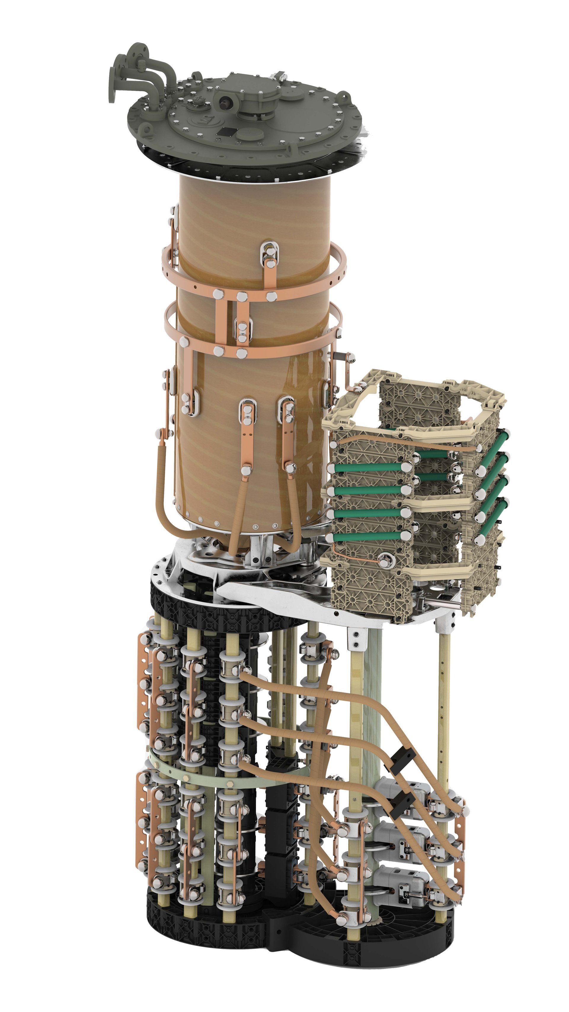
The OLTC design that is normally used for higher ratings and higher voltages comprises a diverter switch (arcing switch) and a tap selector. For lower ratings, OLTC designs in which the functions of the diverter switch (arcing switch) and the tap selector are combined in a selector switch (arcing tap switch) are used.
With an OLTC comprising a diverter switch (arcing switch) and a tap selector (fig. 11), the tap-change operation takes place in two steps (fig. 12). The next tap is first preselected by the tap selector at no load (fig. 12 position a - c). The diverter switch then transfers the load current from the tap in operation to the preselected tap (fig. 12 position d - i). The OLTC is operated by means of a drive mechanism. The tap selector is operated by a gearing directly from the drive mechanism. At the same time, a spring energy accumulator is tensioned, which operates the diverter switch – after release at a very short time interval – independently of the motion of the drive mechanism. The gearing ensures that this diverter switch operation always takes place after the tap preselection operation has finished. The switching time of a diverter switch is between 40 and 60 ms with today’s designs. During diverter switch operation, transition resistors are inserted (fig. 12 position e - g) which are loaded for 20–30 ms, i. e. the resistors can be designed for short-term loading. The amount of resistor material required is therefore relatively small. The total operation time of an OLTC is between 3 and 10 seconds, depending on the respective design.
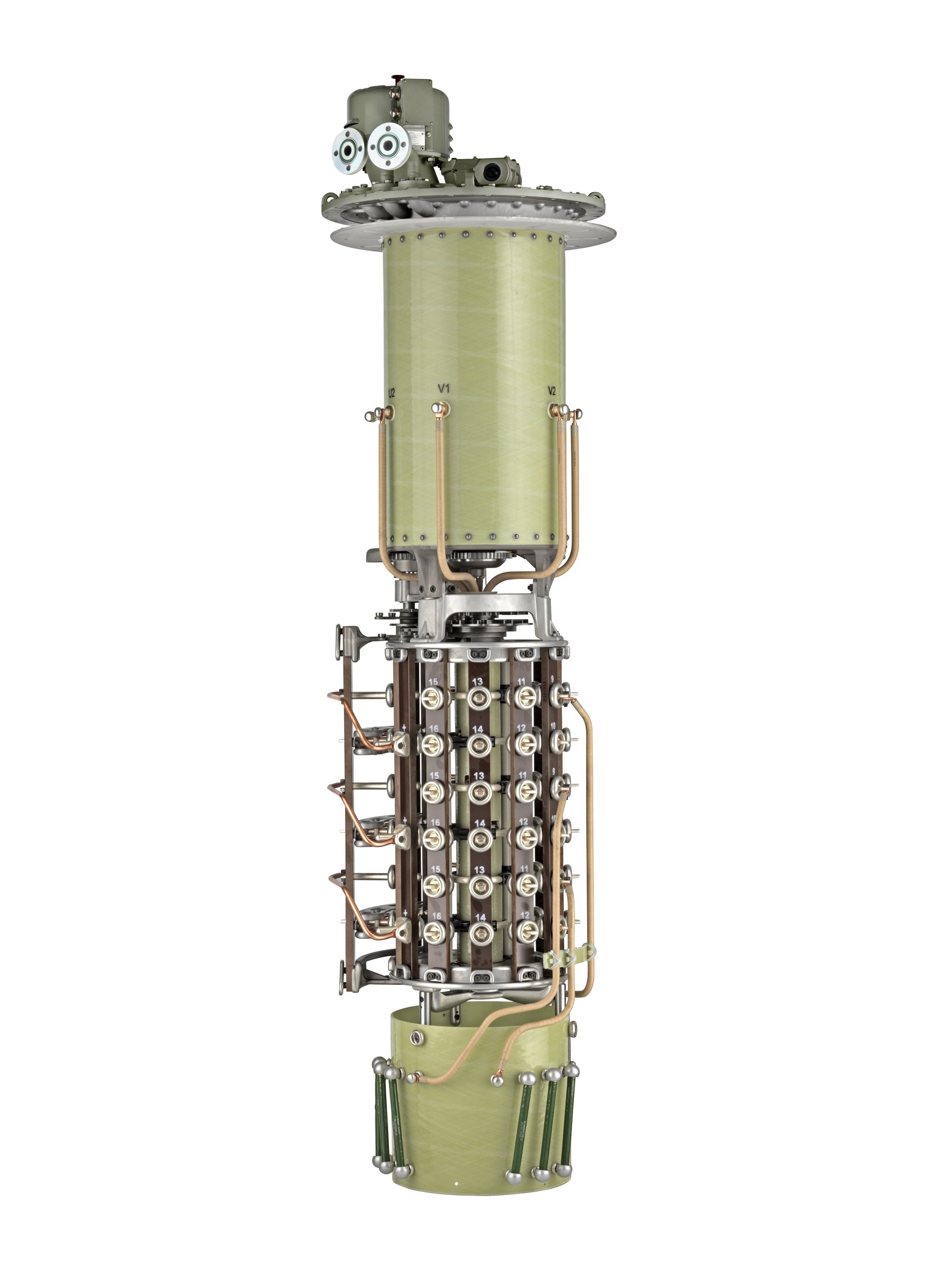
A selector switch (arcing tap switch) as shown in fig. 13 carries out the tap-change in one step from the tap in service to the adjacent tap (fig. 14). The spring energy accumulator, wound up by the drive mechanism actuates the selector switch sharply after releasing. For switching time and resistor loading (fig. 14 position b - d), the above statements apply. The details of switching tasks including phasor diagrams are described in Annex A of [4], [5] and [6].
4.1.2 Reactor oil-type OLTCs
The following types of switching are used for reactor oil-type OLTCs:
- Selector switch (arcing tap switch)
- Diverter switch (arcing switch) with tap selector
All reactor-type OLTCs are compartment types where the preventive autotransformer (reactor) is not part of the OLTC. The preventive autotransformer is designed by the transformer manufacturer and located in the transformer tank.
Today only selector switches (arcing tap switches) for voltage regulators are still in production whereas the reactor vacuum-type OLTCs are going to be the state-of-the-art in the field of power transformers. This oil technology is therefore not further discussed in this paper. For more detailed information about the switching tasks and phasor dia grams of reactor oil-type OLTCs, please see Annex B of [4], [5] and [6].

Figure 11: Design principle – diverter switch (arcing switch) with tap selector OILTAP® M®

Figure 12: Switching sequence of tap selector – diverter switch (arcing switch)

Figure 13: Design principle – selector switch (arcing tap switch) OILTAP® V®

Figure 14: Switching sequence of selector switch (arcing tap switch) OILTAP®
4.2. OLTCs mit Vakuumschalttechnik am Beispiel VACUTAP®
4.2.1 Basic principles of vacuum switching technology
Over the course of the last four decades, vacuum switching technology has become the predominant switching technology in the areas of medium-voltage substations and high-capacity power contactors, and has replaced oil- and SF6-technology. Today the demand for circuit breakers in the medium power voltage segment worldwide is mostly covered by vacuum-type circuit breakers.
Vacuum switching technology also best meets the new application requirements and increased performance demands for OLTCs by end users. Its superiority over competing switching technologies in the low and medium power ranges is based on a number of technical features [7], [8]:
- The vacuum interrupter is a hermetically-sealed system
- There is no interaction with the surrounding medium, despite the arc
- The switching characteristics do not depend on the surrounding medium
- The arc (drop) voltage in vacuum is considerably lower than in oil or SF6
- Low energy consumption
- Reduced contact wear
- Elimination of the insulating medium as the arc-quenching agent
- Elimination of by-products e. g. carbon when using transformer oil
- On-line filter is unnecessary
- Easy disposal
- No aging of the quenching medium
- Constant or even improving switching characteristics throughout the entire lifespan of the vacuum interrupters (getter effect)
- No interaction/oxidation during switching
- High rate of recondensation of metal vapor on contacts extends contact life
- Constantly low contact resistance
- Extraordinary fast dielectric recovery of up to 10 kV/µs
- Ensures short arcing times (maximum one half-cycle) even in the case of large phase angles between current and voltage or high-voltage steepness dU/dt after the current zero (converter transformers) [9].
4.2.2 Application of the vacuum switching technology to on-load tap-changers
When developing a vacuum interrupter for use in an OLTC, the unique parameters are:
- Mechanical life in transformer oil (or any other given insulating medium) for the operating temperature range and expected life-span of the OLTC
- Switching performance
- Contact life
- Physical dimension
Since the early 1970s, vacuum interrupters that complying with the features required by reactor-type OLTCs have been developed. These OLTCs, which are in general external compartment-type designs, did not dictate any special requirements with regard to the physical size of the interrupter. This is not the case with resistor-type OLTCs, which usually have a very compact design. Today, after more than four decades of development, vacuum interrupters have reached an advanced technical performance level. The use of modern clean room and furnace soldering technologies during the production process, and new contact system and material designs are some of the milestones of this reliable product. This has enabled considerably smaller vacuum interrupters to be designed, opening the door for application in resistor-type OLTCs with overall dimensions equivalent to those of conventional resistor-type OLTC designs (see fig. 15 and 16).
In figure 17 the contact wear due to current breaking is shown for conventional copper-tungsten contacts under oil and for vacuum interrupters. The rate is more than one decade smaller for vacuum interrupters (e. g. rate: 1/30 at 1,000 A). Apart from the contact material, the contact geometry is the most important factor for this current range and OLTC applications. This results in contact life, where vacuum interrupters easily reach numbers of switching operations over 600,000 without changing the interrupters.
Investigations in electric arc furnace applications (EAF) cleary demonstrate the superior performance of the special contact material design for use in OLTCs.
Fig. 18 shows the contact system of opened vacuum interrupters after 300,000 EAF-operations in a steel mill in Turkey. The vacuum interrupters were installed in VACUTAP® VRF I 1,300 with a step voltage of 1,400 V and a maximum through-current of 1,200 A.
The contact surfaces were smooth and the total contact wear less than 1 mm. The findings exceeds all MR’s expectations for the contact lifespan and demonstrate that these vacuum interrupters are very far from the end of their lifespan.
As already described in the introduction to chapter 4, the future trend – in other words, the increasing demand for more fire safety, greater environmental compatibility and more freedom of maintenance in transformer technology – must be considered during the design stage of new generations of OLTCs.
Vacuum switching technology, which has no interaction with the surrounding medium and the use of state-of-the-art alternative liquids such as natural and synthetic esters meet all of these requirements.
All the liquid-immersed VACUTAP®-OLTCs presented in chapter 4.2.2 have therefore been designed and tested for mineral oil as well as for selected natural/synthetic esters [10], [11].

Figure 15: OLTCs with tungsten- copper arcing contact system for mineral transformer oil (different scales): Diverter switch contact. system

Figure 15: OLTCs with tungsten- copper arcing contact system for mineral transformer oil (different scales): Selector switch contact system with roller contacts.

Figure 16: Vacuum interrupter designed for different OLTC diverter switches

Figure 17: Comparison of the rates of contact wear of conventional copper-tungsten contacts and vacuum interrupters

Figure 18a: Opened vacuum interrupters after 300,000 EAF-operations

Figure 18b: Opened vacuum interrupters after 300,000 EAF-operations
Power transformers equipped with OLTCs are the main components of electrical networks. The operational reliability of these transformers and their OLTCs is therefore extremely important and must be kept at a high level during their entire lifespan. As shown above, the vacuum-type OLTC is a major improvement for tap-changer technology, however, the vacuum OLTC is nevertheless mechanical switching equipment and requires maintenance.
The principle of a preventive, i. e. periodic maintenance strategy for oil-type on-load tap-changers is based on the time in service or the number of operations, whichever comes first. Only the number of operations applies for the Reinhausen vacuum-type OLTCs, immersed in transformer mineral oil. Time-based maintenance is no longer required.
Except for special applications, the intervals for oil-type OLTCs in star-point application used in network transformers is typically 7 years or between 50,000 and 100,000 operations. For this application, the time in service is the decisive factor. Considering a transformer lifespan of 40 years, 5 maintenance interventions are required for the OLTC. The operating costs are higher when considering delta applications. Depending on conditions, e. g. application of the oil-type OLTC at the line end of the winding and operation with or without an oil filter plant, between 6 to 10 maintenance interventions are necessary (see fig. 32). The maintenance interval for resistor vacuum-type OLTCs is normally 300,000 operations. Thus for a network transformer, this means maintenance-free operation during the lifespan of the transformer (fig. 32).
The maintenance measures required are almost identical for both tap-changer types. The focus is on checks, in other words, the comparison between the actual and desired conditions of mechanically and dielec tric ally stressed components.
The measures required between the maintenance intervals of the vacuum-type OLTCs are minimal and can be easily combined with the usual transformer inspection, and include the following scope of work:
- Visual check of the motor drive unit
- Protection test of the protective relay of the tap-changer
- Monitoring of the tap-changer oil (The dielectric strength and water content are the decisive criteria)
- Regular check of the breather system (silica gel)
Apart from the direct maintenance costs of the OLTC, all associated expenses for handling and special equipment need to be taken into consideration. Additional substantial savings can also be achieved by eliminating the need for on-line filtration systems, which are today widely used for conventional OLTCs. It is an unavoidable fact that an on-line filtration system does generate operating costs during the lifespan of the transformer, in addition to the startup investment.
In addition to drastic savings in maintenance and operating costs, life cycle cost considerations offer several additional advantages for end users:
- Longer, uninterrupted availability of the transformer
- Simplified maintenance logistics
- Protection of environmental and natural resources due to the reduction of oil changes, by-products and worn-out contacts
- Lifespan 40 years
- < 300,000 operations VACUTAP® maintenance-free

Figure 32: Performance of maintenance during lifespan for typical network application
6.1 General requirements
Selection of a particular OLTC will provide optimum technical and economical efficiency if the requirements for operation and testing of all conditions of the associated transformer windings are met. In general, the usual safety margins need not be observed as those OLTCs that are designed, tested, selected and operated in accordance with IEEE and IEC standards [4], [5], [12] are most reliable. See also [13], [14], [15] and [16].
To select the appropriate OLTC, the following key data of the corresponding transformer windings should be known:
- MVA rating
- Connection of tap winding (for wye, delta or single-phase connection)
- Rated voltage and regulating range
- Number of service tap positions
- Insulation level to ground
- Lightning impulse and power frequency voltage of internal insulation
The following OLTC operating data may be derived from this information:
- Rated through-current: Ir
- Rated step voltage: Uir
- Rated step capacity: Pst = Uir x Ir
and the appropriate tap-changer can be determined:
- OLTC type
- Number of poles
- Nominal voltage level of OLTC
- Tap selector size/insulation level
- Basic connection diagram
If necessary, the following tap-changer characteristics should be checked:
- Breaking capacity
- Overload capability
- Short-circuit current (must be checked in the case of phase-shifting applications)
- Contact life
In addition to this, the following two key OLTC stresses resulting from the arrangement and application of the transformer design must be checked:
6.2 Potential connection of tap winding during change-over operation
During operation of the reversing or coarse change-over selector, the tap winding is disconnected momentarily from the main winding. At this point, it assumes a potential that is determined by the voltages of the adjacent windings as well as by the coupling capacities to these windings and to grounded parts. In general, this potential is different from the potential of the tap winding before the change-over selector operation. The differential voltages are the recovering voltages at the opening contacts of the changeover selector and, when reaching a critical level, they are liable to cause inadmissible discharges on the change-over selector. If these voltages exceed a certain limit value (for special product series, the said limit voltages are in the range of 15 kV to 35 kV), measures must be taken regarding the potential control of the tap winding.
Particularly in the case of phase-shifting transformers with regulation at the line end (e. g. fig. 9), high recovery voltages can occur due to the winding arrangement. Figure 33a illustrates a typical winding arrangement of PST according to fig. 9. Figure 33b shows the diagram of this arrangement without limiting measures. As can be seen, the recovery voltages appearing at the change-over selector contacts are in the range of the system voltages on the source and the load side. An OLTC certainly cannot be operated under such conditions. This fact must be taken into account during the planning stage of the PST design [2], [3], [4], [6], [12].
There are three methods of solving the above-mentioned problem:
- One way of decreasing the recovery voltages is to install screens between the windings. These screens must have the potential of the movable change-over selector contact 0 (fig. 9). See Figures 34 a and 34 b.
- The second way is to connect the tap winding to a fixed potential by a fixed resistor (tie-in resistor) or by a resistor which is only inserted during change-over selector operation by means of a potential switch. This resistor is usually connected to the middle of the tap winding and to the current take-off terminal of the OLTC (fig. 35).
- The third possibility is to use an advance retard switch (ARS) as a change-over selector (fig. 36). This additional unit allows the change-over operation to be carried out in two steps without interruption. With this arrangement, the tap winding is connected to the desired potential during the entire change-over operation. As this method is relatively complicated, it is only used for high power PSTs.
The common method for the potential connection of tap windings is to use tie-in resistors. The following information is required to dimension tie-in resistors:
- All characteristic data of the transformer such as: power, high and low voltages with regulating range, winding connection, insulation levels
- Design of the winding, i. e. location of the tap winding in relation to the adjacent windings or winding parts (in the case of layer windings)
- Voltages across the windings and electrical position of the windings within the winding arrangement of the transformer which is adjacent to the tap winding
- Capacity between tap winding and adjacent windings or winding parts
- Capacity between tap winding and ground or, if present, grounded adjacent windings
- Surge stress across half of tap winding
- Service and test power frequency voltages across half of the tap winding

Figure 33: Phase-shifting transformer, circuit as shown in fig. 9 a) Typical winding arrangement with two tap windings b) Recovery voltages (Ur+, Ur-) for tap windings 1 and 2 (phasor diagram)

Figure 34: Phase-shifting transformer, circuit as shown in fig. 9 a) Winding arrangement with two tap windings and screens b) Recovery voltages (Ur+, Ur-) for tap windings 1 and 2 (phasor diagram)

Figure 35: Methods of potential connection (reversing change-over selector in mid-position) a) Fixed tie-in resistor RP b) With potential switch SP and tie-in resistor RP₁d

Figure 36: Phase-shifting transformer – change-over operation by means of an advanced retard switch
6.3 Effects of the leakage impedance of tap winding/coarse winding during the operation of the diverter switch when passing the mid-position of the resistor-type OLTC [6], [12]
During the operation of the diverter switch (arcing switch) from the end of the tap winding to the end of the coarse winding and vice versa (passing mid-position, s. fig. 37 a), all turns of the whole tap winding and coarse winding are inserted in the circuit.
This results in a leakage impedance value which is substantially higher than during operation within the tap winding where only negligible leakage impedance of one step is relevant (fig. 37 b). The higher impedance value in series with the transition resistors has an effect on the circulating current which is flowing in the opposite direction through coarse winding and tap winding during diverter switch operation. Consequently a phase shift between switched current and recovery voltage takes place at the transition contacts of the diverter switch and may result in an extended arcing time.
In order to ensure optimal selection and adaptation of the OLTC to these operating conditions, it is necessary to specify the leakage impedance of coarse winding and tap winding connected in series.

Figure 37: Effect of leakage impedance of coarse winding/ tap winding arrangement a) Operation through mid-position b) Operation through any tap position beside mid-position
For the time being, no alternative to regulating transformers is expected. The tap-changer will therefore continue to play an essential part in the optimum operation of electrical networks and industrial processes in the foreseeable future.
Conventional tap-changer technology has reached a very high level and is capable of meeting most requirements of transformer manufacturers. This applies to all the voltage and power fields of today, which will probably remain unchanged in the foreseeable future. It is very unlikely that, as a result of new impulses to development, greater power and higher voltages will be required. Today, the main concern focuses on service behavior as well as the reliability of tap-changers and how to retain this reliability at a consistently high level during the regulating transformer’s life cycle.
At present, as well as in the foreseeable future, the proper implementation of vacuum switching technology in OLTCs provides the best formula for quality, reliability, and economy that can be achieved for maintenance-free design in the field of OLTCs. Vacuum switching technology entirely eliminates the need for an on-line filtration system and offers reduced downtimes with increased availability of the transformer and simplified maintenance logistics. All this translates into substantial savings for the end user. Consequently, today’s design concepts of OLTCs – resistor and reactor-type OLTCs – are based more and more on vacuum interrupters. The vacuum switching technology used in OLTCs is in fact the state-of-the-art design of today and tomorrow.
The development of new alternative liquids for use in transformers and tap-changers like natural and synthetic esters will lead to new challenges. With the vacuum switching technology in OLTCs, these liquids can be used. Today, it is mainly regulating transformers up to the medium range (< 100 MVA) that are available with alternative insulating liquids used e.g. in offshore applications such as wind farms and drilling platforms. Due to the increase in demand, these applications may be extended to transformers and tap-changers with higher ratings in the future.
As an option to alternative insulating liquids, dry-type distribution transformers with regulation have been available for several years. The OLTC operates in air with vacuum interrupters. These transformers are used for indoor applications with extreme fire hazard and/or pollution requirements, as is the case in metropolitan and special industrial areas. With an extensive range of application-specific products and customized services, the Reinhausen Group provides reliable and economic solutions for efficient power generation and grid connection as well as for industrial processes.
[1] Goosen, P.V. Transformer accessories, (On behalf of Study Committee 12), CIGRE, 12–104, 1996
[2] Kraemer, A. and Ruff, J., Transformers for phase angle regulation, considering the selection of on-load tap-changers, IEEE Trans. Power Delivery, 13 (2), April 1998
[3] IEEE Std C57.135–2001, IEEE Guide for the Application, Specification, and Testing of Phase-Shifting Transformers
[4] IEEE Std C57.131–2012, IEEE Standard Requirements for Tap-Changers
[5] IEC International Standard 60214–1:2014, Tap-Changers, Part 1: Performance requirements and test methods
[6] Kraemer, A., “On-Load Tap-Changer for Power Transformers, Operation, Principles, Applications and Selection,” MR Publication, ISBN 978-3-931954-47-5
[7] Dohnal, D., Kurth, B., “Vacuum Switching, A Well Proven Technology Has Found its Way into Resistance-Type Load Tap-Changers”, in Proc. 2001 IEEE Transmission and Distribution Conference
[8] Dohnal, D., Kraemer, A., Vacuum Switching Technology in On-Load Tap-Changers becomes state of the Art for Regulating Transformers in Proc. CEPSI 2002 Fukuoka; The 14th Conference of the Electric Power Supply Industry
[9] Dohnal, D., Kraemer, A., Shen, D., “HVDC-Applications significantly improved by the use of the new Generation of On-Load Tap-Changers with Vacuum Switching Technology”, CEPSI 2006 Mumbai, The 16th Conference of the Electric Power Supply Industry
[10] Dohnal, D., Frotscher, R., Investigation and Guidelines for the Application of Natural and Synthetic Ester Liquids to Tap-Changers for Power Transformers, CEPSI 2008 Macau, The 17th Conference of the Electric Power Supply Industry
[11] Dohnal, D., Frotscher, R., “The Importance of Alternative Insulating Liquids for Power Transformers and Tap-Changers”, CEPSI 2010 Taipei, The 18th Conference of the Electric Power Supply Industry
[12] IEC International Standard 60214-2:2019, Tap-Changers, Part 2: Application Guide
[13] Grigsby, L. L., “The Electric Power Engineering Handbook”, CRC Press LLC, 2001, pp. 3–184 – 3–204, ISBN 0-8493-8578-4
[14] Harlow, J., “Electric Power Transformer Engineering”, CRC Press LLC, 2004, pp. 3 29 – 3 49, ISBN 0-8493-7104-5
[15] Harlow, J., “Electric Power Transformer Engineering, Sec. Edition”, CRC Press, 2007, pp. 13-1 – 13-32, ISBN: 0-8493-9186-5
[16] Harlow, J., “Electric Power Transformer Engineering, Third Edition”, CRC Press LLC, 2012, pp. 14–1 – 14–48, ISBN 9781439856291